SecurityKISS VPN
SecurityKISS
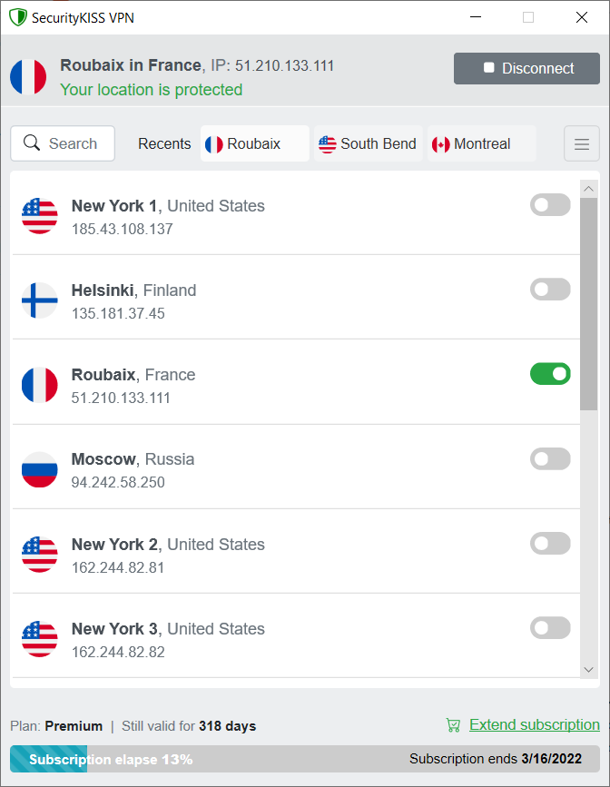
encrypts your internet traffic and tunnels it to our server
located in country of your choice.
No one can discover your real location,
no one can sniff your tunneled traffic.
Lightweight but smart application which just works
No ads, 100% clean! See reviews
Free plan available at full speed!